12 High Voltage Cable Construction Techniques Utilized Globally
- Hüseyin GÜZEL

- Jul 16, 2024
- 13 min read
Updated: Jul 23, 2024
This technical article discusses twelve different methods for laying high-voltage cables. Out of these, four are deemed conventional and eight are considered progressive. Various utilities and companies worldwide are utilizing these methods to varying extents. Four of the twelve methods are considered more conventional.

This is primarily because the vast majority of companies worldwide depend on at least one of these tools for constructing and laying high-voltage cables. Their affordability, ease of use, and accessibility to resources (both materials and equipment), along with competent business owners, have made them widely used for decades.
One may wonder if a rigid or flexible system is better for installing cables when using specific procedures (tunnels, microtunnels, bridges, pipe jacking, etc.). A stiff design prevents the wire from bending or twisting and instead uses its strong internal compressive force to absorb thermal expansion.
The lateral deflection of the cable enables it to adapt to expansion movements within a flexible system. This design ensures that no component undergoes severe strain during movement, which could otherwise reduce the cable's fatigue life.
Table of Contents:
1. Cable Trenches (or Direct Burial)

This method involves excavating a trench to physically lay the cables (refer to Figure 1). The protective covering over the cables typically extends 1 meter or more. The most common installation configurations are the trefoil formation for voltages up to 170 kV and flat formation for voltages above 170 kV.
A key benefit of this approach is the flexibility it offers in altering the cable route to circumvent unforeseen obstacles.
The depth of the trench ensures that the cables are usually covered by at least one meter of soil, which is often a regulatory mandate but may also depend on the short-circuit current levels. Cables are generally laid in a trefoil pattern, and for every meter, a suitable non-corrosive cladding or rope is used to wrap the cables, preserving the trefoil configuration during the backfilling of the trench.
For cables with ratings between 220 and 500 kV, depending on their capacity, a flat formation is another type of laying pattern that is frequently employed.
Beginning with the protective bottom layer mentioned earlier, the trench's backfilling materials consist of sand, specialized backfill, or potentially lean concrete. It is not customary to backfill with excavated soil or concrete. For enhanced mechanical protection of the cables, a weak mix can be used instead of the standard backfill. In numerous countries, a special backfill, referred to as controlled backfill, is employed to create an environment with low thermal resistivity, which helps in the dissipation of heat from the power cables, thereby allowing for a higher power rating of the connection.
The integration of fiber-optic cables, or optical fibers, into HV cables may not be common practice yet, but it will certainly offer advantages in the future, such as enabling continuous thermal monitoring of the connection.
Figure 1 – Direct burial of cables in trenches

2. Cable Ducts
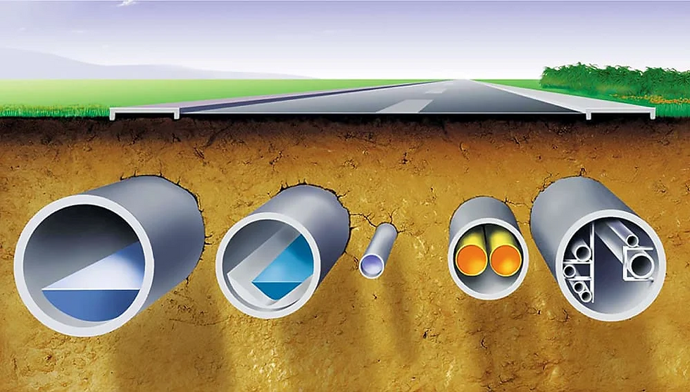
This installation technique involves laying ducts or pipes within trenches—created by horizontal drilling or other methods—and subsequently threading cables through them. These conduits may be composed of PVC, concrete, polyethene (PE), steel, or fibre-reinforced epoxy (FRE), with PVC and PE being the most frequently used.
The ducts or pipes can be filled with substances such as air, bentonite, cement, sand, or water. Generally, each duct contains a single cable and is filled with either air, bentonite, or another similar material.
In urban areas of large cities, duct systems are often paired with manholes for convenience, allowing civil engineering tasks to be conducted independently of electrical work. This separation is advantageous as it permits cable maintenance or replacement with minimal interference to local traffic and business operations.
In sparser areas, joint bays may be employed instead of manholes to reduce costs.
High-voltage cable circuits are typically installed in dedicated duct banks, with one cable per duct. For lower voltages, it's possible to place three cables in a single duct to save costs. Moreover, two circuits, which amount to six cables, can be installed within the same duct bank. However, it is not recommended to install more than two circuits to avoid the risk of cable damage from accidental excavation, thereby enhancing the availability of the underground system while preserving an adequate cable load rating.
Installing cables in ducts is considered one of the safest methods for protecting against short circuits. It is important to highlight that sufficient earth cover over the duct bank is necessary to guarantee public safety. Additionally, it should be noted that manholes may pose a safety hazard in case of a cable or joint failure.
Empty ducts may serve as a reserve for future cables, provided that the sheath bonding is appropriately designed. It is also feasible to place fiber optic communication cables within the same duct bank.
Figure 2 – Laying cables in ducts

3. Laying in Troughs
The troughs usually consist of precast concrete segments, which are typically placed inside a trench. Afterward, the cables are installed within the trough (refer to Figure 3). It is common to fill the troughs with sand and to lay three wires per trough. The soil excavated is generally used as backfill around the troughs.
The trough may be constructed by assembling precast sections, each about one meter long, or by continuously pouring concrete to create a unified structure. The upper edges of the sides can be shaped to support a structural cover made of concrete, steel, or fiber-reinforced plastic, which is intended to shield the installed cable.
Troughs are usually filled with a specialized backfill like select sand or a weak mortar mix, which aids in heat dissipation. Once the trough channel is in place, cable installation can proceed similarly to that in an open trench, either by pulling the cables or laying them between junctions or from a joint to a termination point. Afterward, covers are placed.
Figure 3 – Laying cables in troughs

4. Cable Tunnels
Tunnel boring machines can excavate tunnels with diameters exceeding 2-2.5 meters. These tunnels serve a variety of purposes beyond just cable installation and are not limited by technology in terms of their length. The method of arranging cables inside the tunnel, whether on steel trays or encased in concrete, depends on the tunnel's intended use, such as for metro systems or other utilities.
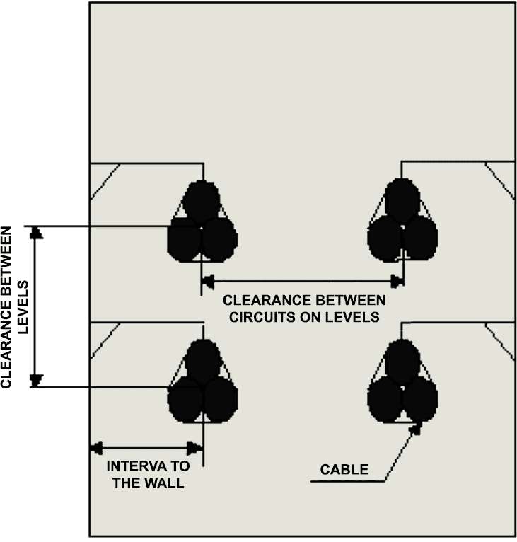
Tunnels often share space with other utilities like gas or water. A widely used installation method features a flexible design, arranging cables in a trefoil formation (refer to Figure 4). Among four tunnels, only one is fitted with a cooling system. This technique is commonly adopted for cables with a voltage rating over 170 kV, thus becoming the preferred method.
Tunnels are used for accommodating cables when numerous circuits must be installed along a specific route, and providing the required transmission capacity through direct burial or ducts is difficult. They are also used in urban areas where the feasibility of using alternative methods at ground level is impractical.
Tunnels can be constructed using the open-cut method, shield method, or pipe jacking method. The pipe jacking method is detailed in Section #10. Both the shield method and pipe jacking method have similar geometries.
The sole difference between them lies in their individual construction techniques.
Open-Cut Method: The open cut method is a technique utilized in tunnel construction. It begins with the excavation from the ground surface, proceeds with the construction of the tunnel at the specified location, and concludes with the restoration of the ground surface using backfill materials. The most common approach is the full-face procedure.
Shield Method: The Shield method is utilized when the Open-cut method is impractical. It is particularly useful in areas with heavy road traffic or when constructing tunnels at significant depths, where surface excavation is challenging. Employing this method helps prevent disruption to existing underground infrastructure, including telephone cables, gas lines, water mains, sewer systems, and subway tunnels.
Cables within tunnels may be set up in a rigid layout, often utilized when space is constrained, or in a more prevalent flexible arrangement. In the latter, cables are arranged with both vertical and horizontal snaking to accommodate various practical considerations. As an alternative, empty troughs can be used, incorporating horizontal snaking.
Figure 4 – Laying cables in the tunnel

5. Microtunneling
Microtunneling is employed as an installation technique in scenarios where open trenching is impractical, such as when traversing obstacles like railways, rivers, duct banks, and highways.
This technique utilizes a thrust-jacking station to push prefabricated pipe sections, which match the diameter of the final pipeline, through the ground from a launch pit. Tunnel boring is fully mechanized, using remotely controlled microtunnel boring machines at the leading edge of the pipes. This technique allows for the construction of narrow horizontal tunnels with diameters ranging from 0.3 m to 1.2 m.
Typically, the lengths of these sections do not exceed 150 meters. If the drilling length is too extensive, it can be split into two segments using a central work shaft and two lateral exit shafts.
Microtunnels are usually designated for a single user. Cables are often pulled through ducts that are installed in the microtunnel upon its completion. If required, the ducts and the space between the ducts and the microtunnel can be filled.
Microtunneling is employed in scenarios where open trenching is impractical. This trenchless technology requires a thorough geological understanding of the area. A comprehensive geological study and subsoil survey, including the presence or absence of the groundwater table, must be conducted before detailing the civil engineering work.
Figure 5 – Microtunnelling

Once the microtunneling and cable installation is complete, maintenance is not required. The tunnel tubes offer excellent mechanical protection, making external damage highly unlikely and negating the need for mechanical repairs. Should the cable fail internally, it can be easily extracted from the duct and replaced.
The narrow width of the ducts precludes the use of cable joints for repairing the tunnel section.
6. Cable Shafts
Cable shafts, which are either circular or rectangular excavations, are constructed vertically or at an angle less than 30 degrees from the vertical. These shafts are typically excavated at the beginning and end points of a microtunnel. Within these shafts, cables are usually installed on a steel framework, and the shaft's length dictates whether a rigid or flexible system is used.
The most common installation methods feature a versatile design with cables arranged in a trefoil pattern. Shafts are frequently used in hydraulic generation facilities to transport power from underground machinery to the beginning of the overhead lines. In urban areas, shafts are also utilized along cable routes where cables need to be guided through deep tunnels and linked to overhead lines or substations. Cables may be secured to the walls of the shafts or to metal structures.
Multiple circuits can be installed within the same shaft; in such cases, walls or specialized structures are used to mitigate potential damage in case of a circuit malfunction. Where present, joints are usually situated horizontally within chambers designed specifically for this purpose.
Shafts are often used as vents in production plants, and the air temperature must be considered during typical operations when designing the installation architecture.
Figure 6 – Shaft in front of a cable micro tunnel

Shafts are often built as components of power plant or tunnel projects, and the design for cable installation needs to consider the existing infrastructure. Calculations are sometimes necessary to confirm that the current facilities can bear the weight of the cables and the structures needed.
For Foundation Fieldbus (FF) cables, it is essential to install junction chambers strategically along the shaft to adhere to the maximum cable length requirements. The size of these chambers should accommodate the dimensions of the joints, the quantity of cables, and the structures that will be constructed.
7. Bridges
This approach facilitates the circumvention of expensive and technically intricate methods when traversing particular or sensitive areas. The cables are positioned either inside or outside the bridge, contingent on the bridge's structural design. The most common installation practices feature a versatile design with cables arranged in a trefoil pattern.
Bridges that already exist are frequently utilized where the cable path intersects with rivers, railways, traffic junctions, and the like. Some bridges inherently offer space for cable installation, whether within the bridge structure or along the sidewalk. For concrete bridges, the cables are placed in precast troughs on the sidewalk, where they are laid out directly.
Single-core cables are arranged in a trefoil formation to minimize the magnetic field. The trough is filled with cement-bound sand, known for its low thermal resistivity. The limited space frequently hinders the construction of joint pits. On steel profile bridges, cables may be installed within steel profiles or along cable ladders, necessitating enhanced protection, especially at the piers.
Cables may be directly cleated onto the bridge or threaded through ducts. Significant deliberation is required before deciding to use an existing bridge for crossing. The designer must consider dynamic mechanical stresses from vibrations, elongation, and bending at connections, along with environmental stresses like sunlight, heat, and wind pressure.
In the construction of new bridges, provision for future cables should always be made. Cast-in ducts facilitate easy cable routing across the bridge. Nonetheless, the cables' offset at the piers remains a critical factor.
Figure 7 – Bridge for high voltage cables

8. Mechanical Laying
This method, adapted from the conventional trench technique, is suitable for laying underground cables. It involves excavating a trench, simultaneously installing the three-phase cables, along with any necessary grounding and telecommunication cables, and then backfilling.
When used in conjunction with weak-mix mortar, it offers the following advantages:
Good cable protection from external harm.
Good control of the cable’s direct thermal environment.
Good environmental protection in the event of a short-circuit.
Trench size is reduced when compared to conventional techniques, and
Reduced work duration
Three options exist for organizing the mechanical laying site:
Option #1 – A mechanically excavated narrow trench is used for the separate laying of cables: traditional methods are employed for laying and backfilling after the trench excavation.
Option #2 – Trench excavation, cable laying, and occasionally backfilling are all performed mechanically: a machine carries out these tasks.
Option #3 – Trench excavation, cable laying, and backfilling are continuous and mechanized processes. Using this method, trench excavation, cable laying, and occasionally trench backfilling can be performed simultaneously in a continuous operation along the entire length of a homogeneous section of the link (joints must be prepared in advance). This technique is typically employed for voltages below 170 kV.
Cables are commonly buried directly in a trefoil configuration, with at least one meter of cover.
Figure 8 – Mechanical laying of high-voltage cables

This technique requires specialized, expensive, and heavy equipment. Transporting this equipment from one site to another needs careful planning in terms of cost and time.
9. Horizontal Drilling
This technique has developed from directional drilling methods employed in the oil industry and is used to traverse significant obstacles such as rivers, railway lines, highways, etc., as well as for longitudinal drilling. The process involves three stages: drilling the pilot hole, backreaming (which is the process of pumping and rotating the drill string while concurrently withdrawing it from the hole), and installing the final pipe(s). Drilling mud, typically bentonite, removes cuttings to the surface, reduces friction, stabilizes the borehole, and cools the drill bit.
Generally, mud is filtered and reclaimed for reuse in a closed circuit. The soil type is crucial when considering this approach. After placement, cables are drawn into the pipes. Typically, three PE ducts are installed in a single bore, with one cable per duct.
They are filled with either air or bentonite.
Guided horizontal drilling, also referred to as guided boring, is a trenchless construction method that enables faster product installation with minimal disturbance to the surrounding urban and suburban areas.
Drilling operations can commence by entering an already excavated launching pit or by initiating from the road or ground surface, commonly referred to as a surface launch.
Watch Video – How to Install Cables Under the Road Using Horizontal Drilling
10. Pipe Jacking
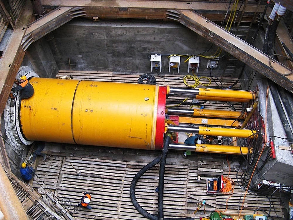
Pipe jacking involves thrusting prefabricated pipes of the desired final cross-section through the ground. An excavation for a work pit or shaft is made to fit the jacking apparatus and the pipe segment to be installed. As the pipe jacking progresses, earthworks are carried out, either by hand or mechanically, based on the specified diameter (Figure 9).
The initial segment of the pipe might feature a steel cutting edge that slices through the soil while safeguarding the workers excavating it. Pipe jacking is applicable for pipes with diameters from 0.4 meters to 3.2 meters. This method is advantageous for spans exceeding 100 meters, and pipe jacking operations can span distances of 500 to 600 meters.
Pipes are commonly constructed from concrete or steel. Cables are laid within tunnels or microtunnels, contingent on their size. When required, the ducts and the intervening space between the ducts and the pipe may be filled.
Pipe jacking is considered an eco-friendly method of installation as it does not adversely impact the environment. The surplus soil, which is equal to the volume of the pipe, is removed, thus preventing the displacement of existing and compacted soil. However, pipe jacking is unsuitable for hard soils like limestone, sandy shale, or granite, and is not recommended for heterogeneous soils containing blocks of clay, flint, and sandstone.
Prior to selecting the pipe jacking technique, it is essential to investigate the soil type and composition. Without this analysis, pipe jacking may face delays due to obstructions, necessitating a labor-intensive and time-consuming process to manually remove the blockage at the front of the initial pipe by cutting it into pieces. This procedure cannot be performed with pipes smaller than 800 mm in diameter.
Excavation from the surface, or employing explosives within the pipe when feasible, is the only way to avoid abandoning the installation. Under such conditions, initiating a new pipe jacking operation at an alternate depth or location becomes necessary. Additionally, cathodic protection should be taken into account when performing pipe jacking with steel pipes.
Figure 9 – Pipe jacking for HV cables

11. Embedding
The embedding method includes excavating the riverbed using a barge or an amphibious vehicle to embed the pipes or cables directly (refer to Figure 10). This technique necessitates halting or rerouting river traffic when traversing navigable waterways during the excavation and installation processes.
Recent technological advancements in embedding machines and ancillary equipment, such as remotely operated vehicles (ROVs), have made cable burial feasible in various methods, up to considerable depths, and in nearly any type of riverbed. To reduce expenses, embedding should be confined to areas where the risk of cable breakage justifies the cost.
When there is minimal risk and ample power supply for the link, considering cable repair as a favorable option is advisable; costs will be incurred only if the cable sustains damage.
Certainly, the cost of repair, weighed against its probability, should be measured against the cost of protection. The success of this approach can vary based on the context, like in a brief span with significant human activity, including shipping and anchoring.
While a comprehensive embedding might be preferable, in a long connection with minimal local activity, an exposed cable—except in areas requiring specific protection—could be significantly more cost-effective, even when considering the potential repair expenses.
Figure 10 – Embedding pipes or cables in the riverbed

12. Use of Existing Structures
Sometimes, it may be decided to use existing structures like racks or trays, or even repurpose old utility ducts previously used for water, gas, or pipelines, for cable housing. Consequently, it's crucial to perform a detailed inspection and thorough cleaning of these structures, especially the ducts.
Finding alternative configurations for high voltage power lines is becoming increasingly difficult, especially in urban or protected areas. The use of existing structures offers an attractive solution for landscape integration challenges and can greatly reduce costs and initial delays.
Reference: Integration of a new HV underground cable system in the network by Cigre


Good job. Thanks a lot.