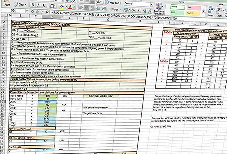
Power Factor (PF) Correction Calculations for Power System
- Hüseyin GÜZEL

- Mar 28, 2024
- 2 min read
Power Factor Correction Using Static Capacitor
The power factor is a measure of how effectively electrical power is being converted into useful work output. A low power factor indicates inefficient use of electricity and can result in increased energy consumption and higher electricity bills.

Static capacitors are connected in parallel to the inductive loads (such as motors, transformers, fluorescent lights) in the system. These capacitors help to offset the reactive power drawn by the inductive loads, thereby improving the power factor.
By improving the power factor, power factor correction reduces the amount of reactive power flowing through the system, which results in several benefits including:
Reduced electricity bills due to decreased losses in the distribution system.
Increased system capacity, as less current is required to deliver the same amount of real power.
Improved voltage regulation and stability.
Reduced stress on electrical equipment, leading to longer lifespan and lower maintenance costs.
Overall, power factor correction using static capacitors is an effective way to optimize the efficiency and performance of electrical systems.

Calculation formulas as follows:
Q1 = I losses + Cu losses
Q2 = PkW · (Tanφ1 – Tanφ2)
I losses = 2% · Str
Cu losses = USC% · Str
Q = Q1 + Q2
Where:
Q1 = Reactive power to be compensated at the terminals of a transformer due to no load and load losses.
Q2 = Reactive power to be compensated due to total reactive components of lighting, power and mechanical loads.
Q = Overall reactive power to be compensated to achieve target power factor.
I losses = Transformer no load losses = Iron core losses.
Cu losses = Transformer load losses = Copper losses.
Str = Transformer rating (KVA).
P = Maximum demand load on the Main distribution board (kW).
φ1 = Inverse cosine of power factor before compensation.
φ2 = Inverse cosine of target power factor.
Usc% = Short circuit percentage impedance voltage of the transformer.
Power Factor values assumptions before compensation:
For lighting outlets = 0.96
For power outlets and receptacles = 0.8
For motors = 0.8
Inputs = Transformer size + Transformer type + kVA Max. demand load for the whole system + PF before compensation + Target value of PF.
Outputs = Reactive power to be compensated at the terminals of a transformer due to no load and load losses.
Reactive power to be compensated due to total reactive components of lighting, power and mechanical loads
Overall reactive power to be compensated to achieve target power factor + circuit breaker size required to protect the capacitor bank.


Comments