Basics of Electrical Bus Protections
- Hüseyin GÜZEL
- Jan 16, 2022
- 5 min read
Updated: Feb 2, 2022
Overcurrent, Differential and Undervoltage
When we examine electrical protection schemes, the best place to start is with electrical bus protections, as they are the easiest to protect. They utilize the fundamental concept of the overcurrent relay (Figure 1). An overcurrent relay is an electromagnetic device in which current in the coil surrounding a metal core produces a magnetic flux in the core.
When there is a sufficient current flow, the flux will attract the armature (metal flap), which will move to close the attached contacts.

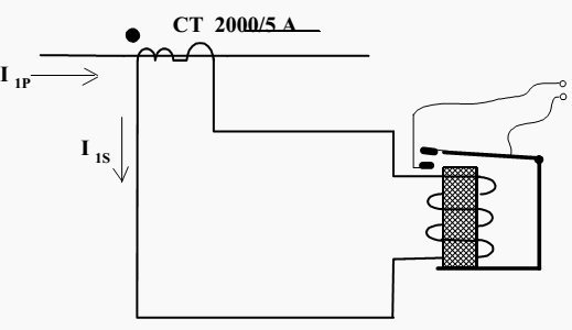
Two other items are indicated in the diagram. One is the direction of CTs. If current I1P flows in the primary towards the primary spot mark, simultaneously output current I1Swill flow out of the CT at the secondary spot mark
.
This is an important concept to remember.
!!! Current Transformers (CTs) transform the current in magnitude, but retain the same waveform and phase relationship.
One can picture the current going in as I1Pand out as I1Sinstantly reduced in size by a factor of 2000/5. The second point to note is the CT ratio (2000/5 A). This is standard notation that 2000 Amps in the primary will produce 5 Amps on the secondary
Bus Differential Protection
The differential protection utilizes the overcurrent relay just discussed. For ease of description, we will indicate only one phase of a three-phase system, as the other phases are identical.
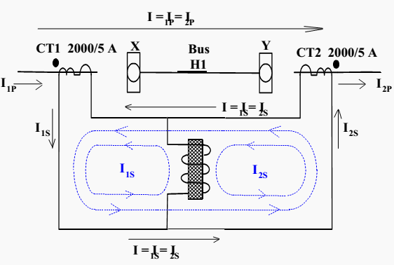
The differential relay is fed by CTs on the outside of the protected bus. Recalling the spot convention of CTs, one can see in Figure 2 below, that if current I1p flows into the bus, then an equivalent current I1s will flow in the secondary winding of CT1. Similarly current I2p will flow out of the bus with a corresponding I2s flowing in the secondary (note direction).
"If the bus is healthy current in equals current out and there will be a circulating current in the secondary circuit as shown. No current will flow in the overcurrent relay.
Note that the current flow in the overcurrent relay is equal to the difference (where differential relay gets itís name) in the input currents. In this case, they are equal and the differential current is zero.
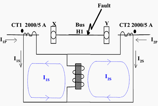
If the bus in Figure 2 happens to a fault (either phase to phase or phase to a ground fault), the current entering and leaving the bus will not be the same. Hence the difference seen by the relay (I1S – I2S) will not be zero.
If the fault is of high enough magnitude to pickup the overcurrent relay the differential protection will operate to trip breakers X and Y, plus block any reclosure of these breakers, initiate breaker failure protection and any other actions required by that specific protection zone.
Figure 3 shows the current directions for the most severe fault, an internal bus fault fed from both ends of the bus. If you consider the figure carefully you will notice that any number of breakers or transformers could be added to the bus. Care would have to be taken to ensure the CT ratios and spot marks were correct and that the secondary circuits were added in parallel.
Figure 4 gives an example of what it would look like if a transformer were fed off the bus.

Bus Overcurrent Backup
Normally bus protection would be made up of two high-speed differential relays that we have just discussed. This would form a duplicated or A and B bus protection. Refer to previous Figure 2 for configuration.
"For low-voltage buses (13.8kV and below) there often is no breaker failure protection provided on the breakers (X and Y in the figure above). In such a case duplicate (A and B) protections cannot be used.
Zone protection with duplicate protections and no breaker failure protection will only work if the breakers never fail. Thus one of the two protections has to be made into a backup, to cover the case where the breaker might not open. This creates a larger overlapping zone as shown by Figure 5.
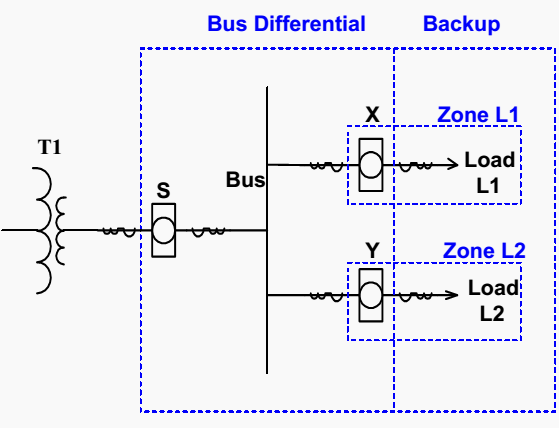
In Figure 5, you can see the standard bus differential zone and the extra bus backup zone that includes the loads L1 and L2 supplied off the bus.
Suppose an electrical fault (phase to phase or phase to ground) or overload occurs on feeder L1. The protection for L1 should operate to trip breaker X. If breaker X does not trip within a certain time the bus backup protection will operate to open supply breaker S and remove all supply from the bus.
A close-up of the bus backup protection is shown in Figure 6 below
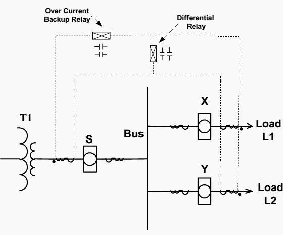
The overcurrent backup relay will see the total current supplied to the bus, whereas the differential relay only sees the difference between supply current and load current as discussed previously. The relay settings for overcurrent backup protections are somewhat difficult and usually employ an instantaneous and timed component.
After all, the objective is that breakers X and Y should clear the fault before the backup protection operates to trip the main supply breaker S.
// The instantaneous overcurrent setting has to be above the total expected current inrush or loading expected on the bus but below the minimum bus fault level. For coordination, the setting also has to be also higher than any individual load setting.
If this cannot be obtained the instantaneous element is blocked.
The timed overcurrent setting has to coordinate with all of the loads fed from the bus to allow the separate protections (Zone L1, L2 in Figure 9) to operate first.
Bus Ground Faults
Bus phase to ground faults is far more common than phase to phase or three-phase faults. They are generally due to the breakdown of insulation by some foreign material or moisture. Due to the severe effect on the connected loads as well as structural damage, these have to be instantaneously cleared from the electrical system.
!!! The differential relay previously discussed is utilized to protect the bus against this type of fault.
Bus Undervoltage Protection
Bus Undervoltage protection (sometimes called no-volt trip) is supplied on many buses for two reasons:
1| Many loads, especially motors, are susceptible to low voltage. As the voltage supply to a motor decreases, the motor will attempt to deliver the same amount of torque for a given load and will draw higher currents to do this. This will result in excessive heating of the motor windings, resulting in insulation damage and reduced machine life
2| Another benefit of this type of protection is to prevent all loads from automatically restarting at the same time when the voltage to a system is restored. Loads are usually introduced slowly to allow the generator to stabilize its power production before more loads are placed on the generator (there are thermal limits on rates of loading/unloading of turbine generators anyway, which help in this situation).
If the loads are all automatically reconnected at once to a re-energized bus, the voltage on that bus will likely drop and the loads will likely trip again on undervoltage. Another danger of automatic re-loading if the voltage is quickly restored is that the supply and load voltages will be out of phase, resulting in current surges and mechanical stresses on the machine.
Undervoltage protection can be achieved by an electromagnetic relay (an example is shown in Figure 7). This relay holds the armature to the coil as long as the voltage remains above the desired amount, keeping the normally open contacts of the relay closed.
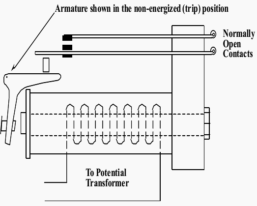
If the voltage drops, the coil can no longer hold the armature and the relay contacts will open. In this type of protection, there will also be a time delay built in (usually by a timer) to prevent operation during voltage transients (i.e., if the voltage is quickly restored, the trip will not occur).
The voltage drop and time delay are chosen such that re-energizing the load will not result in excessive demands on the system.


Comments