Operating conditions significantly affect the lifespan of capacitors. Therefore, it is essential to choose different categories of capacitors with varying levels of endurance based on these conditions.
In addition to the rules and standards, the production of electrical switchboards for the LV compensation requires consideration of specific constraints.
Table of Contents:
Benefits of reactive energy management
Savings on the electricity bill
Increasing available power
Reducing the installation size
Power Factor Correction Guidelines
Calculation of Reactive Energy Based on the Application
Power Factor Correction for Transformer no-load compensation
Power Factor Correction where Load and present Power Factor is Known
Selection of the compensation mode
Global Compensation
Compensation by Sectors
Compensation of Individual Loads
Selection of the compensation type
Fixed Compensation
Automatic Compensation
Dynamic Compensation
Taking account of operating conditions and harmonics
Harmonics in Electrical Installations
Influence of Harmonics on Capacitors
Key Points Discussed in The Document
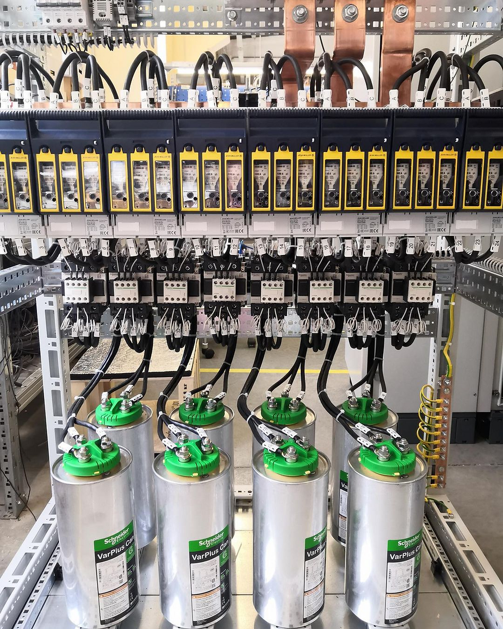
1| The Compensation Modules:
The VarplusCan and VarplusBox capacitors: Their positioning must ensure proper ventilation. Their sizing must take into account ambient conditions (harmonics, temperature, etc…)
The contactors: They must be suited to capacitor control. Schneider Electric has designed and tested specific contactors for this application.Their control voltage must be monitored in order to prevent rapid reclosing.
2| The Detuned Reactors (DR)
They must be chosen according to harmonic stresses and installed in order to avoid, as far as possible, capacitor temperature rise. The DR temperature sensor must be connected so that the step can be disconnected if the temperature is too high
3| Ventilation
It must be efficient in order to keep the operating temperature lower than the maximum permissible temperature of components.
4| The Power Factor Controller
Its functions must be adapted to the capacitor bank characteristics: number and power of steps, sequence, etc. The time delay must be adapted to capacitor discharge time.
5| Low Voltage Network
Network characteristics, and in particular network harmonic distortion, must absolutely be taken into account when choosing capacitors and detuned reactors (if any).
6| Tests to be done after production of the bank
At the end of the manufacturing process, an LV switchboard must undergo various routine inspections and tests in the factory, following an established programme.
The switchboard must comply with :
the appropriate standards
the design file (drawings, diagrams and specific requirements)
manufacturer mounting instructions
in-house instructions.
7| Maintenance must be done every year
One month after energising, check all contactor terminal tightening torques.
Annual checks
General cleanliness of the equipment
Filters and ventilation system
Terminal tightening torques
Proper working order of switching and protective devices
Temperature in the premises: -5 °C to +40 °c max - for normal designs
Capacitor capacitance: Consult us if the capacitance value has changed by more than 10 %
Applicable Standards and Definitions
1| Applicable Standards
IEC: 61921 (Power Capacitors- Low voltage power factor correction banks) is the international standard applicable for Low Voltage Power Factor Correction Banks and Automatic Power Factor Correction (APFC) equipment intended to be used for power factor correction purposes, equipped with built-in switch gears and control gears. The guidelines for the design, installation, operation and safety of APFC panels are followed based on this international standard.
The design of the Low Voltage Power Factor Correction banks and accessories shall comply with the following standards
IEC60831: Part 1 & 2-Shunt power capacitors of the self-healing type for a.c systems having rated voltage up to and including 1kV.
IEC 60439-3: Low voltage switchgear and control gear assemblies. Particular requirements for low-voltage switchgear and control gear assemblies are intended to be installed in places where unskilled persons have access to their distribution boards.
IEC 60947: Low Voltage Switchgear Part 2: Molded Case Circuit Breakers & Air circuit Breakers Part 4: Power Contactors Part 4-3: Thyristor Switch
IEC 60269: LV Fuses ● IEC 60076-6: Reactors
IEC 60529: Degree of protection provided by enclosure (IP code)
IEC 60044-1: Current transformers.
IEC 60664-1 / IEC 61326: Power Factor Controller
2| Definitions
The design of the APFC equipment involves the following major parts and the selection of these depends very much on the above system conditions.
Enclosure: protects the APFC system components against the external solid or liquid particles and also provide protection for human beings.
PFC Controller: This is the brain of the APFC system, which switches ON / OFF the steps depending on the kvar required in order to maintain the PF close to unity.
Bus bars: The bus bar is the electrical conducting path, to which all the components in the APFC system are connected.
Switchgears: Switchgears are the devices which control the circuit under faulty and normal conditions. Switchgear protects the APFC system against faulty conditions.
Cables: Cables are used to connect various components in the steps. Proper cable sizing has to be considered for a particular step depending on the rated current and the operating temperature in order to link the various components of the system. Cables loop the power circuit & control circuit in the system.
Protection devices: Protection has to be provided to safeguard the capacitors and other components due to abnormalities in the system. The incoming switchgear of the APFC system should be tripped by protective devices.
Reactors: Reactors are used in steps as detuned filters and are connected in series with capacitors. It must be designed to withstand fundamental and harmonic currents.
Capacitors: Capacitors form the core component in APFC equipment and play a vital role in power factor correction. Proper selection of capacitors is very much necessary to comply with the applications.
Reactive Energy Guidelines
1| Principle of reactive energy management
All AC electrical networks consume two types of power: active power (kW) and reactive power (kvar):
The active power P (in kW) is the real power transmitted to loads such as motors, lamps, heaters, computers … The electrical active power is transformed into mechanical power, heat or light.
The reactive power Q (in kvar) is used only to supply the magnetic circuits of machines, motors and transformers.
The apparent power S (in kVA) is the vector combination of active and reactive power.
In this representation, the Power Factor (P/S) is equal to cosφ.
The circulation of reactive power in the electrical network has major technical and economic consequences. For the same active power P, a higher reactive power means a higher apparent power and thus, a higher current must be supplied.
- The circulation of active power over time results in active energy (in kWh).
- The circulation of reactive power over time results in reactive energy (kvarh).
- In an electrical circuit, the reactive energy is supplied in addition to the active energy.
Due to this higher supplied current, the circulation of reactive energy on distribution networks results in:
Overload of transformers,
The higher temperature rise of the supply cables,
Additional losses,
Large voltage drops,
Higher energy consumption and cost,
Less distributed active power.
For these reasons, there is a great advantage to generating reactive energy at the load level in order to prevent the unnecessary circulation of current in the network. This is what is known as “Power Factor Correction”.
This is obtained by the connection of capacitors, which produce reactive energy in opposition to the energy absorbed by loads such as motors.
The result is a reduced apparent power, and an improved power factor P/S’ as illustrated on the diagram on the left.
The power generation and transmission networks are partially relieved, reducing power losses and making additional transmission capability available.
The reactive power is supplied by capacitors.
No billing of reactive power by the energy supplier.
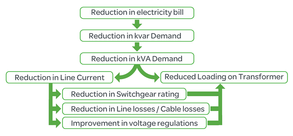
2| Benefits of reactive energy management
Optimized management of reactive energy brings economic and technical advantages.
2.1 Savings on the electricity bill:
Eliminating penalties on reactive energy and decreasing kVA demand,
Reducing power losses generated in the transformers and conductors of the installation.
Example//
Loss reduction in a 630 kVA transformer
PW = 6,500 W with an initial Power Factor = 0.7.
With power factor correction, we obtain a final Power Factor = 0.98
The losses become: 3,316 W, i.e. a reduction of 49%
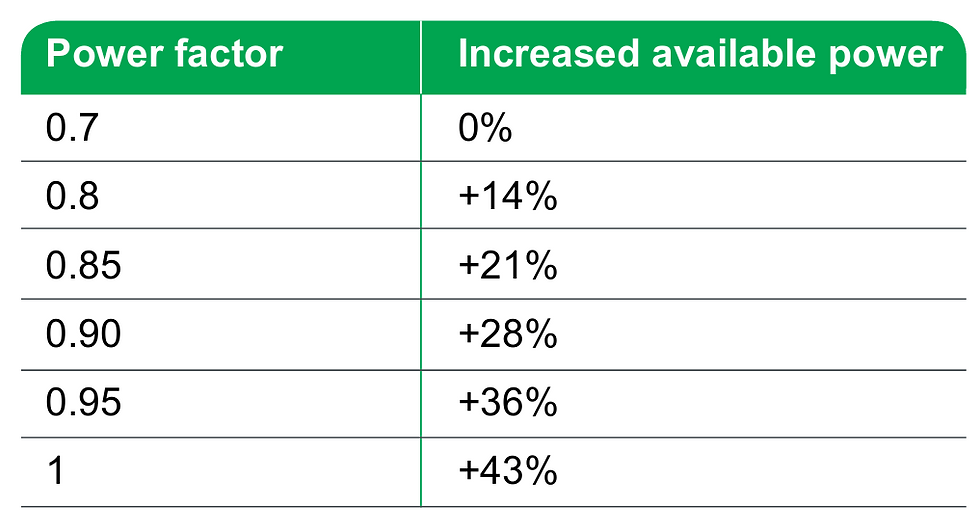
2.2 Increasing available power:
A high power factor optimizes an electrical installation by allowing a better usage of the components.
The power available at the secondary of an MV/LV transformer can therefore be increased by fitting power factor correction equipment at the low voltage side.
Table 1 shows the increased available power at the transformer output by improvement of the Power Factor from 0.7 to 1.
Table-1: Increasing available power
2.3 Reducing the installation size
Installing power factor correction equipment allows the conductors cross-section to be reduced, since less current is absorbed by the compensated installation for the same active power.
The table-2 on the left shows the multiplying factor for the conductor cross-section according to the different values of the power factor.
Table-2: Cable cross-section multiplying factor

3| Reducing the voltage drops on installation
Installing capacitors allows the voltage drops to be reduced upstream of the point where the power factor correction device is connected. It avoids the overload of the network and allows the diminution of harmonics so that no overrating of the installation is necessary.
Power Factor Correction Guidelines
The selection of the Power Factor Correction equipment can follow a 4-step process:
Calculation of the requested reactive energy
Selection of the compensation mode
Selection of the compensation type
Taking account of operating conditions and harmonics
1| Calculation of Reactive Energy Based on the Application
1.1 Power Factor Correction for Transformer No-load Compensation
The transformer works on the principle of Mutual Induction. The transformer will consume reactive power for magnetizing purposes.
The following equivalent circuit of the transformer provides the details of reactive power demand inside the transformer:

1.2 Power Factor Correction where Load and Present Power Factor is Known
The objective is to determine the requested reactive power QC (kvar) to be installed, in order to improve the power factor cosφ and reduce the apparent power S.
For φ’ < φ, we’ll get: cosφ’ > cosφ and tanφ’ < tanφ.
This is illustrated in the diagram above.

QC can be determined from the formula: QC = P. (tanφ - tanφ‘), which is deduced from the diagram.
QC: power of the capacitor bank, in kvar
P: active power, in kW
tanφ: tangent of the phase angle - before compensation,
tanφ‘: tangent of the phase angle - after compensation.
The parameters φ and tanφ can be obtained from the billing data, or from direct measurement in the installation.
The following table-3 can be used for direct determination.
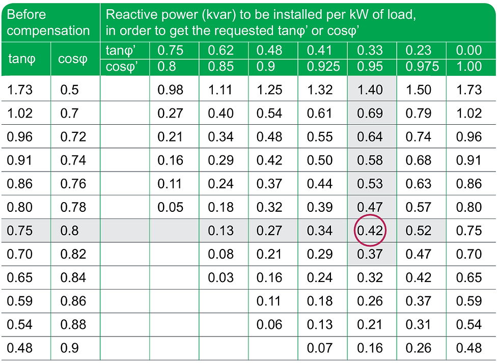
Example //
Consider one 1000kW motor with cosφ 0.8 (tanφ = 0.75).
In order to get cosφ’= 0.95, it is necessary to install a capacitor bank with a reactive power equal to k x P, i.e.: Qc = 0.42 x 1000 = 420 kvar
2| Selection of the compensation mode
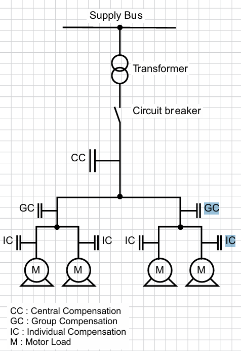
The location of low-voltage capacitors in an installation constitutes the mode of compensation, which may be global (one location for the entire installation), by sectors (section-by-section), at load level, or some combination of the latter two. In principle, the ideal compensation is applied at a point of consumption and at the level required at any instant.
In practice, technical and economic factors govern the choice.
The place for connection of capacitor banks in the electrical network is determined by:
Global objective (avoid penalties on reactive energy, relieve of transformer or cables, avoid voltage drops and sags), GC
Operating mode (stable or fluctuating loads), IC
Foreseeable influence of capacitors on the network characteristics,
Installation cost.
2.1 Global Compensation
The capacitor bank is connected at the head of the installation to be compensated in order to provide reactive energy for the whole installation. This configuration is convenient for stable and continuous load factors.
2.2 Compensation by Sectors
The capacitor bank is connected at the head of the feeders supplying one particular sector to be compensated. This configuration is convenient for a wide installation, with workshops having different load factors.
2.3 Compensation of Individual Loads
The capacitor bank is connected right at the inductive load terminals (especially large motors). This configuration is well adapted when the load power is significant compared to the subscribed power. This is the technical ideal configuration, as the reactive energy is produced exactly where it is needed, and adjusted to the demand.
3| Selection of the compensation type
Different types of compensation shall be adopted depending on the performance requirements and complexity of control:
Fixed, by connection of a fixed-value capacitor bank,
Automatic, by the connection of a different number of steps, allowing the adjustment of the reactive energy to the requested value,
Dynamic, for compensation of highly fluctuating loads.
3.1 Fixed Compensation
This arrangement uses one or more capacitor(s) to provide a constant level of compensation. Control may be:
Manual: by circuit-breaker or load-break switch,
Semi-automatic: by contactor,
Direct connection to an appliance and switch with it.
These capacitors are applied:
At the terminals of inductive loads (mainly motors),
● At bus bars supplying numerous small motors and inductive appliances for which individual compensation would be too costly,
● In cases where the load factor is reasonably constant.
3.2 Automatic Compensation
This kind of compensation provides automatic control and adapts the quantity of reactive power to the variations of the installation in order to maintain the targeted cos φ. The equipment is applied at points in an installation where the active power and/or reactive power variations are relatively large, for example:
At the busbars of a main distribution switch-board,
At the terminals of a heavily loaded feeder cable.
Where the kvar rating of the capacitors is less than or equal to 15% of the supply transformer rating, a fixed value of compensation is appropriate. Above the 15% level, it is advisable to install an automatically-controlled bank of capacitors.
Control is usually provided by contactors. For compensation of highly fluctuating loads, fast and highly repetitive connection of capacitors is necessary, and static switches must be used.
3.3 Dynamic Compensation
This kind of compensation is requested when fluctuating loads are present, and voltage fluctuations should be avoided. The principle of dynamic compensation is to associate a fixed capacitor bank and an electronic var compensator, providing either leading or lagging reactive currents.
The result is a continuously varying and fast compensation, perfectly suitable for loads such as lifts, crushers, spot welding...
4| Taking account of operating conditions and harmonics
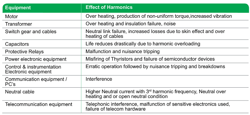
When considering operating conditions and harmonics in electrical power systems, it’s essential to understand how harmonics can affect the performance and reliability of the system. Here are some key points to consider:
4.1 Harmonics in Electrical Installations
The presence of harmonics in electrical systems means that current and voltage are distorted and deviate from sinusoidal waveforms.
Harmonic currents are currents circulating in the networks and which frequency is an integer multiple of the supply frequency.
Harmonic currents are caused by non-linear loads connected to the distribution system. A load is said to be non-linear when the current it draws does not have the same waveform as the supply voltage. The flow of harmonic currents through system impedances in turn creates voltage harmonics, which distort the supply voltage.
The most common non-linear loads generate harmonic currents using power electronics, such as variable speed drives, rectifiers, inverters, etc…. Loads such as saturable reactors, welding equipment, and arc furnaces, also generate harmonics.
Other loads such as inductors, resistors and capacitors are linear loads and do not generate harmonics.
4.2 Influence of Harmonics on Capacitors
Capacitors are particularly sensitive to harmonic currents since their impedance decreases proportionally to the order of the harmonics present. This can result in a capacitor overload, shortening steadily its operating life. In some extreme situations, resonance can occur, resulting in an amplification of harmonic currents and a very high voltage distortion.
Amplification of Harmonic currents is very high when the natural resonance frequency of the capacitor and the network combined happens to be close to any of the harmonic frequencies present.
This situation could result in severe overvoltages and overloads which will lead to premature failure of capacitors.
To ensure good and proper operation of the electrical installation, the harmonic level must be taken into account in the selection of the power factor correction equipment. A significant parameter is the cumulated power of the non-linear loads generating harmonic currents.

Document: | Guide for the Design and Production of LV Power Factor Correction Cubicles – Panel Builder Guide by Schneider Electric |
Format: | |
Size: | 7.35 MB |
Pages: | 76 |
Download: |


Comments