System Grounding – Definition and Different Types
Grounding is a term frequently used in the electrical industry, encompassing both "equipment grounding" and "system grounding". Equipment grounding involves connecting the earth's ground to non-current-carrying conductive materials like conduits, cable trays, junction boxes, enclosures, and motor frames.
"System grounding" refers to the connection of the earth's ground to the neutral points of current-carrying conductors, such as the neutral point of a circuit, a transformer, rotating machinery, or a system, either directly or through a current-limiting device. Figure 1 demonstrates the two types of grounding.

What Is a Grounded System? A grounded system is one where at least one conductor or point, typically the middle wire or the neutral point of transformer or generator windings, is deliberately connected to the ground, either directly or via an impedance, as per IEEE Standard 142-1991 1.2.
Common grounding methods used in industrial and commercial power systems include solid grounding, low-resistance grounding, high-resistance grounding, and ungrounded systems.
What Is the Purpose of System Grounding? System grounding involves the deliberate connection of a phase or neutral conductor to the earth. This is done to control the voltage to the ground within predictable limits. It also facilitates a current flow that enables the detection of an unwanted connection between system conductors and the ground, known as a ground fault.
Figure 1 – System and Equipment Groundings

What Is a Ground Fault? A ground fault occurs when there is an undesired connection between system conductors and the ground. These faults can often remain undetected, wreaking havoc on industrial production processes. They can cause power shutdowns and equipment damage, disrupting product flow and resulting in significant productivity losses. Unnoticed ground faults also present serious health and safety hazards to workers, including risks of equipment failure, fires, and electrical shocks. Such faults can inflict considerable damage on both equipment and processes, leading to a direct impact on profitability during fault conditions.
Having over-current protection is essential; however, it may not be sufficient on its own. Over-current protection is designed to interrupt circuits for specific current levels. Yet, certain ground faults, especially low-level arcing faults, can cause considerable damage and become a source of ignition without reaching the threshold needed to trigger the over-current protective device.
An Exmple Setup: 11kV/0.415kV Transformer Supplying A LV (415V) Switchboard
You have a setup with an 11kV/0.415kV transformer supplying a low voltage (415V) switchboard. The total load is approximately 280kVA, primarily consisting of three-phase motors initiated DOL, with a minority on VSD. You're considering the use of an MCCB with shunt trip as the incomer to offer thermal and magnetic protection. You're inquiring whether earth-fault and under-voltage protections are essential for this setup.
Figure 2 - 11kV/0.415kV Transformer Supplying A LV (415V) Switchboard

What is the best way of achieving earth-fault protection economically as well, e.g., CB-CT, residual CTs?
The most economical method for achieving earth-fault protection is to use a combination of circuit breakers (CB) with current transformers (CT), or residual current transformers (residual CTs). These systems can provide effective fault detection and interruption in a cost-efficient manner.
Determining the settings for earth-fault and under-voltage relays requires first deciding on the system earthing for the 415V supply. Typically, this would be a solidly grounded system; however, this necessitates tripping during an earth fault, which exposes the system to significant arc flash hazards.
Applying high-resistance earthing allows for the continuation of power supply to the motors even in the event of an earth fault, without the risk of arc flash hazards related to ground faults. Considering the transformer's size and the load, a neutral-earthing resistor with a 2A let-through at 230V would be adequate.
The detection of an earth fault can now be achieved by simply monitoring the voltage to ground from each phase, or by observing the current passing through the resistor with a sensor and an earth-fault relay.
This relay can be adjusted for a 1A pickup, which is quite cost-effective. For additional details on high-resistance grounding, technical information is available.
Figure 3 – Low-Voltage MCC feeders

Medium voltage switchgear is the collective arrangement of circuit breakers, fuses, and switches designed to protect, control, and isolate electrical equipment. It is commonly utilized in utility transmission and distribution systems, as well as commercial and industrial settings. Conversely, low voltage distribution is the process of transporting electrical energy from distribution transformers to the electricity meters of final consumers, functioning at a voltage level that matches the mains voltage of electrical appliances.
Choosing solid grounding over high-resistance grounding allows for the selection of an earth-fault relay setting of 100A. This setting can be achieved using an earth-fault element on the incoming MCCB, equipped with built-in CTs and a loose neutral sensor. The time delay setting should be minimized to limit fault damage, ideally between 0.1 to 0.5 seconds.
Consideration of time/current coordination issues with load-side protective devices is necessary to prevent nuisance tripping of the MCCB, a common issue with SG systems. The under-voltage function should be set to 80% of the nominal value.
When a significant portion of the load consists of motors operating under single-phasing conditions, the open phase may regenerate, making it challenging to detect if the under-voltage setting is less than 80%.
Zone-Selective Interlocking (ZSI)
How can zone-selective interlocking reduce the arc flash hazard from ground faults? Zone-selective interlocking can mitigate the arc flash hazard from ground faults by enabling the nearest upstream circuit breaker to a short-circuit or ground fault to override any programmed delays for coordination. This protection scheme reduces arc flash energy by tripping the breakers more quickly than the programmed settings. The arc flash hazard is measured by the incident energy released in an arc flash at a specific location, which is expressed in calories per square centimetre and determined through an arc flash hazard analysis. Since the incident energy is directly proportional to the duration of the arcing fault, reducing the arc flash hazard is possible by decreasing the time delay settings of the phase and ground-fault overcurrent protective devices.
The continuity of service is crucial in many facilities and is enhanced by the time-current coordination between phase overcurrent devices and ground-fault devices. Without such coordination, an upstream breaker may trip prematurely, disrupting more of the facility than necessary. In severe instances, the main breaker of the plant could trip.
The disadvantage of time-current coordination lies in the additional time delay imposed on upstream protective devices. This approach tolerates more damage from upstream arcing faults to prioritize service continuity.
Figure 4 – Low-Voltage Switchgear Incident Due to Arc-flash Incident
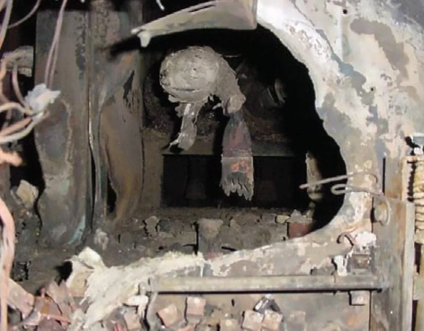
Today, the awareness of arc flash safety has heightened; engineers and electricians are re-evaluating the tripping time delays in the upstream distribution system. The priority of arc flash safety surpasses that of service continuity on switchboards that necessitate inspection while energized.
Zone-selective interlocking (ZSI), or zone-selective instantaneous protection (ZSIP), provides an outstanding solution to this issue. It enhances arc flash safety in the upstream plant distribution system while preserving service continuity.
Zone Selective Interlocking (ZSI) is utilized in both phase over-current devices, for the short-time protection function, and in ground-fault protective devices. It is incorporated into the electronic trip units and relays of circuit breakers. In a ZSI system, a breaker that detects a fault will trip immediately without intentional delay unless it receives a restraint signal from the downstream breaker; if restrained, the breaker will delay tripping until the preset time expires.
The downstream breaker sends a restraint signal upstream only if it detects the fault itself, meaning it does so for faults situated downstream of both breakers. In the case of a fault at point Y, the subfeeder breaker will send a restraint signal to the feeder breaker, which in turn will restrain the main breaker. Consequently, the main and feeder breakers will delay tripping until the timeout. During this delay, the subfeeder breaker will clear the fault.
Zone-selective interlocking, while available for decades, has not seen widespread use due to the sufficiency of time-current coordination; upstream damage in the distribution system was considered an acceptable compromise. Nonetheless, the current emphasis on enhancing arc flash safety is leading to the adoption of shorter trip times.
The investment in ZSI twisted-pair control wiring for connections between switchboards, panelboards, and motor control centers is now deemed valuable as it enhances arc flash safety while maintaining service continuity.
Neutral Grounding Resistor Installed on 3 Transformers Working in Parallel
A local utility system includes three parallel step-down transformers from 13.2kV to 4.16kV (delta/Y system), which are solidly grounded. All transformers supply power to a shared 5kV switchgear bus, equipped with two tie breakers and outgoing feeders with vacuum circuit breakers. The system's design required limiting the ground fault, taking into account the limitations of cable shielding.
Current line-to-ground fault values range from 16kA to 20kA, varying by location. A viable solution is to install a Neutral Ground Resistor (NGR) on the existing transformers to limit the line-to-ground fault current to below 1000A.
1. What are the pros and cons of that solution?
The advantages include limiting the fault current to 1000A, which provides time to isolate the faulted feeder while keeping all non-faulted feeders operational. The disadvantage is the increased line-to-ground fault current that occurs when a tie is closed.
Instead of having 1000A, there are 2000A when two transformers are connected via a tie if you are paralleling. If you are limiting the fault current to 1000A, the resistor will have to be rated for a short-duty cycle; 10 seconds would probably be the most common.

It would be beneficial to specify the coefficient of resistivity when specifying the resistor material. Please look at NGR Guide HERE for more information.
Another downside is the need to isolate the faulty circuit. If the fault current had been limited to 5A or 10A per transformer, it might have been possible to avoid tripping during a ground fault.
Figure 5 – Combined Low-Voltage Switchgear with Cast-Resin Distribution Transformer

2. What type of difficulties could be faced when it comes to relay settings?
When dealing with relay settings, one might encounter various difficulties such as mechanical wear, environmental factors like temperature and dust, water ingress, excessive current or voltage, coil failure, and age-related degradation of the component. Additionally, issues can arise from incorrect understanding of relay functions, typographical errors in setting configurations, and incompatibility of setting files during field adjustments.
Relay settings can be complex, as they require consideration of all potential scenarios. Are the relays in parallel? Are the ties open or closed? Aside from these considerations, the process should be manageable.
3. What would be more advisable: to install a resistor on all three transformers or one common ground resistor?
Determining whether to install a resistor on all three transformers or a single common ground resistor depends on the specific requirements of your electrical system. Installing individual resistors can provide benefits such as controlling transient over-voltages, simplifying ground fault location, and offering improved protection for both the system and equipment. On the other hand, a common ground resistor can reduce maintenance time and expenses, enhance safety for personnel, and improve lightning protection. It's essential to consider the advantages of each method in the context of your system's design and operational needs.
The sole safe method to employ a single resistor involves connecting all neutrals together and installing one resistor on the common neutral to ground. However, I would advise against this practice, as it is impossible to consider the transformer entirely isolated, dead, or safe. This is because the neutral has the potential to rise to 2400V unexpectedly in the event of a ground fault.
You would have to use isolation switches in order to service the transformers, and that can be costly.

Title: | Resistance Grounding: Ask The Experts by iGard |
Format: | |
Size: | 4.10 MB |
Pages: | 40 |
Download: |
Comentarios