The Structure and Connection of LV/MV/HV Capacitor Banks
- Hüseyin GÜZEL

- Aug 6, 2024
- 7 min read
The Structure and Connectivity of LV/MV/HV Capacitor Banks involve various configurations and protective measures to ensure efficient operation and safety in electrical systems. These banks are integral in power factor compensation, voltage regulation, and harmonic filtering across different voltage levels. Each setup has its specific advantages and requires appropriate connection modes and protection mechanisms to handle potential internal faults and external electrical conditions.

Compensation Capacitors
Compensation Capacitors are utilized across a wide range of electrical installations. They can be found in high-voltage transmission and distribution systems, transformer substations, and at different points within low-voltage installations. Consequently, capacitors must be manufactured to meet a broad spectrum of technical specifications, accommodating power requirements from a few kvar to several Mvar.
The installation of capacitors in electrical systems serves multiple purposes. Besides the widely recognized role in power factor compensation, they also enhance voltage regulation on transmission lines by mitigating voltage drops and augmenting the capacitive component of predominantly inductive lines.
Capacitor banks consist of capacitor units that are wired, safeguarded, and linked together in various connection modes suitable for each specific application. Each connection mode presents its own set of benefits and drawbacks.
It is also important to mention that various detection systems, such as current or voltage relays and controllers, are employed alongside capacitor banks. These systems are crucial for identifying (at the alarm threshold) and mitigating hazardous conditions that may arise, such as imbalance or cascading damage.
Table of Contents:
1. Connections of Capacitor Banks
1.1 Delta Connection
The delta connection is the most frequently utilized mode for connecting capacitor banks with voltages below 12 kV. Particularly favoured in distribution installations, this setup offers the highest reactive power within the smallest dimensions. It inherently self-compensates in the event of current imbalances or phase shifts between phases, such as when powerful single-phase loads are present.
This connection mode presents a limitation: it does not permit the filtering of zero sequence components, such as third-order harmonics and their multiples.
Capacitors should be insulated to withstand the full voltage across phases, and in the event of a breakdown, the resulting fault current will be high due to it being a phase-to-phase short circuit.
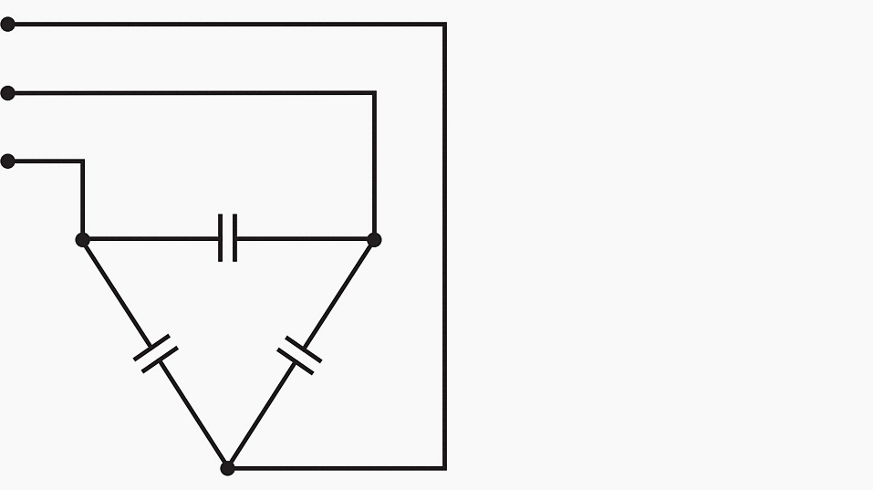
A delta connection is utilized for capacitor banks in low to medium-voltage applications, providing maximum reactive power in a compact size and balancing compensation naturally in the presence of current unbalance or phase shifts.
1.2 Star Connection, Neutral Not Connected
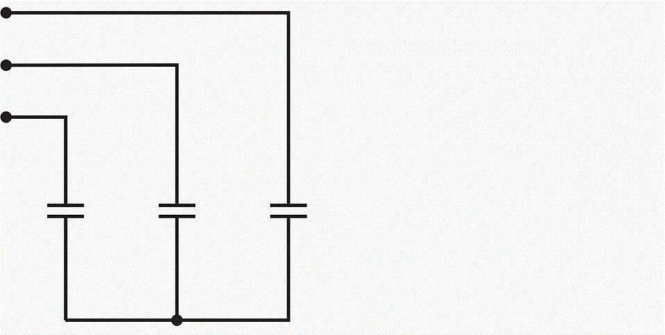
A star connection offers several technical benefits compared to a delta connection, yet it is not as economically advantageous. It has the capability to impede zero sequence currents, for instance. Since the capacitors experience phase-to-neutral voltage, their value needs to be tripled to achieve the equivalent reactive power provided by a delta connection.
The insulation voltage should be rated for the phase-to-phase voltage to prevent the breakdown of one branch from causing subsequent breakdowns in other branches.
The primary disadvantage of this layout is that it may fail to detect the loss of capacitor elements, resulting in load imbalance and lack of compensation. Consequently, a double star connection is often preferred.
1.3 Double Star Connection, Neutral Not Connected
This wiring configuration is appropriate for capacitors of all powers and voltages. It maintains the benefits of a star connection while incorporating a protection mode that allows for the detection of internal faults.
In addition to increasing the bank's capacity, this allows the use of capacitors that are insulated solely for phase-to-neutral voltage.
An imbalance protection device, consisting of a transformer and a current relay, continuously monitors the current imbalance between the two neutral points and, if necessary, initiates the disconnection of the bank.
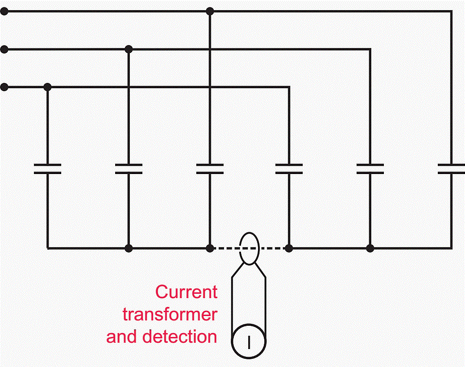
High-voltage capacitor banks consist of basic capacitors, typically arranged in multiple series-parallel configurations, to deliver the necessary electrical properties for the apparatus.
The nominal insulation voltage of a capacitor bank is determined by the number of groups connected in series, whereas the power is contingent on the number of elementary capacitors connected in parallel within each group.
1.4 Star and Double Star Connections, Neutral Earthed
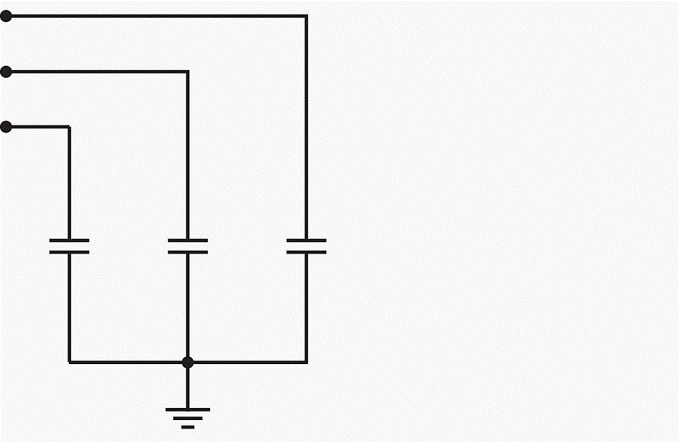
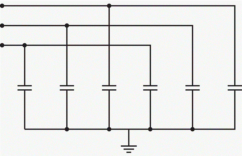
Connections with an earthed neutral offer enhanced protection against transient overvoltages, such as lightning, and general electromagnetic disturbances. However, faults due to internal breakdowns or the loss of a supply phase can generate resonances and zero sequence currents.
These configurations necessitate protection against overvoltages and imbalances.
1.5 H Connection
An H connection is suitable for both delta and star configurations in single-phase or three-phase connections. The schematics illustrate a branch connection either between two phases or between a phase and neutral.
This wiring configuration is designed for high-power HV capacitor banks. In three-phase capacitor banks, monitoring of the unbalance occurs on each individual phase, offering enhanced sensitivity in measuring current imbalances.
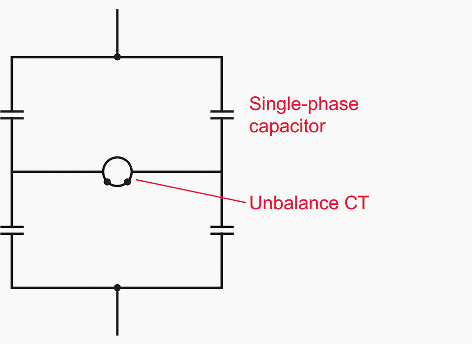
The H connection of a capacitor bank can be utilized for delta or star single-phase or three-phase connections. This wiring is intended for high-power HV capacitor banks, and for three-phase banks, the unbalance is monitored on each phase.
2. Internal Faults In Capacitor Banks
2.1 Protection Through Pressure Monitoring Devices
Capacitors may be safeguarded by a pressure switch that detects elevated pressure within the case, resulting from the failure of the basic capacitances, in addition to or as an alternative to fuses, based on the necessary protection conditions. This increased pressure activates a contact that signals the measured state to initiate the disconnection of a protective device.
2.2 Protection Using Internal Fuses
When an internal fault impacts one or more elementary capacitors, it's crucial to identify and rectify this fault swiftly to prevent an avalanche breakdown of the bank. Should a fault occur in an elementary capacitor, the associated internal fuse will remove the defective element. Considering the vast number of elementary capacitors comprising the device, the consequent power loss is insignificant (less than 2%).
In conjunction with fuses, protection that ensures symmetry maintenance allows for the identification of imbalances indicative of several defective capacitors. The adjustment threshold, determined accurately by the manufacturer, establishes the upper limits of operation to guarantee optimal reliability and service continuity.
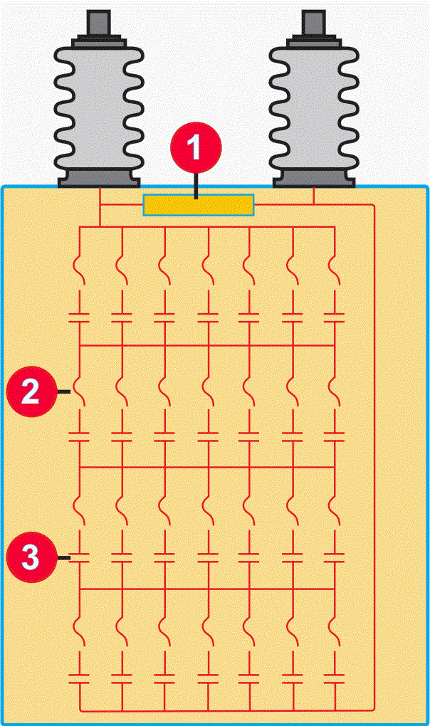
Where:
Discharge Resistor
Internal Fuse
Elementary Capacitance
2.3 “All Film” HV Capacitors
Each basic capacitor is constructed with two aluminium foils serving as electrodes, separated by a polypropylene film with high dielectric strength. Once dried, processed, and vacuum-impregnated with an eco-friendly, non-chlorinated liquid dielectric, all interconnected components are encased in stainless steel, featuring porcelain terminals or insulated lead-ins at the top for device connection.
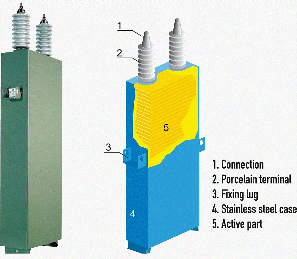
The "all film" capacitor technology boasts superior quality features, including outstanding resistance to electrical fields, minimal ohmic losses that reduce temperature increases, significantly longer lifespan compared to earlier paper-based technologies, and robust resistance to transient overcurrents and overvoltages.
The polypropylene film, serving as a liquid dielectric, boasts exceptionally high chemical stability, significant gas absorption capacity, and robust partial discharge extinction capacity (with a flash point around 150°C), guaranteeing complete insulation between electrodes.
Table 1 – Technical Characteristics
Average loss factor | on energization: | 0.15 W/kvar |
after 500 hours’ operation: | 0.10 W/kvar | |
The average variation in capacitance as a function of temperature. | 2×10⁻⁴ °C | |
Operating frequency | Standard: | 50 Hz |
On request: | 60 Hz | |
Permissible overloads | Permanent: | 1.3 In |
Permissible overvoltages | 12 h/24 h: | 1.1 Un |
30 min/24 h: | 1.15 Un | |
5 min/24 h: | 1.2 Un | |
1 min/24 h: | 1.3 Un |
3. The Structure and Composition of LV Capacitor Banks
A distinction exists between fixed-value capacitor banks and "step" (or automatic) capacitor banks, which possess an adjustment system that tailors the compensation to the fluctuating consumption levels of the installation.
3.1 Fixed Capacitor Banks
Devices with constant power are ideal for individual compensation at the terminals of receivers, such as motors and transformers, or in installations where the load remains steady with minimal fluctuation.

3.2 Step Capacitor Banks with Automatic Regulation
This device allows for the adaptation of reactive power supply to match consumption variations, maintaining optimal compensation. It is particularly useful in scenarios where reactive power consumption fluctuates significantly and is substantial compared to the transformer's power. These conditions often occur at the terminals of primary low-voltage distribution boards or at the source of high-power outgoing lines.
Step capacitor banks consist of several steps connected in parallel. Each step includes a capacitor or a group of capacitors and a contactor. The switching on and off of the entire capacitor bank or parts of it is managed by an integrated power factor controller.
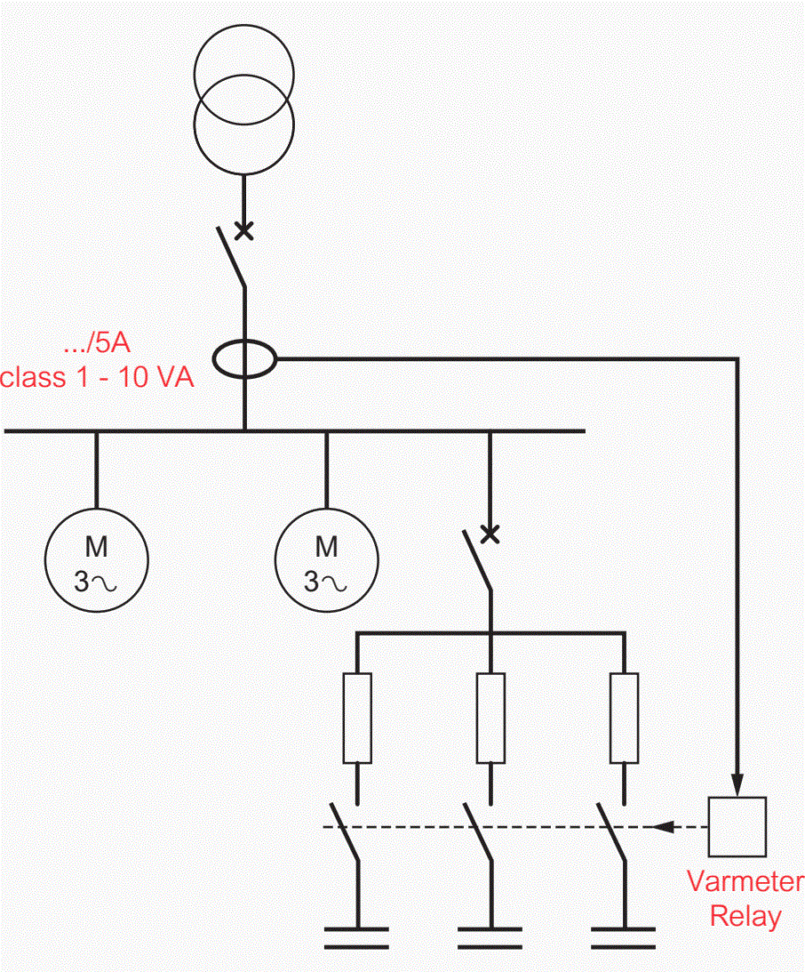
The capacitors will therefore only be activated after the motor starts. Likewise, they may be disconnected before the motor is switched off.
Capacitors will thus be activated only after the motor has started, and they can be disconnected prior to the motor being turned off. The benefit of this system lies in its capacity to fully compensate for the motor's reactive power when at full load. If multiple capacitor banks of this kind are to be installed within the same system, an optional damping reactor is recommended.
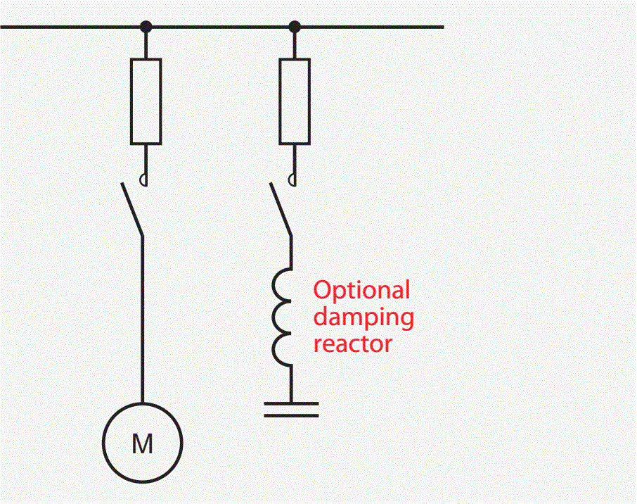
3.3 Capacitor Banks With Separate Control
Separate switching of a capacitor bank may be required to prevent overvoltages, which can occur due to self-excitation or when a motor starts, by employing a specialized device.
Rheostat,
Change of coupling,
Auto-transformer,
etc.
3.4 Conventional Rules for Selecting Capacitor Bank Technology
Fixed compensation carries the risk of over-compensation, leading to abnormally high operating voltages. In contrast, automatic compensation prevents permanent overvoltages caused by over-compensation, especially when the system load is very low. This ensures a stable operating voltage and avoids the extra costs associated with billed reactive energy.
When the capacitors' power (measured in kVAR) is less than 15% of the transformer's power (measured in kVA), selecting a fixed capacitor bank is certainly the most cost-effective solution. Conversely, if the capacitors' power exceeds 15% of the transformer's power, it is necessary to opt for a stepped capacitor bank with automatic regulation.
Reference: | Electrical Energy Supply by Legrand |
Format: | |
Size: | 5.8 MB |
Pages: | 155 |
Download: |


Comments